THE INFORMATION IN THIS DOCUMENT DESCRIBES CEILING FAN WIRING. SUCH CIRCUITS CONTAIN ELECTRICITY THAT CAN INJURE OR KILL YOU. IMPROPER WIRING CAN START A FIRE. CAPACITORS CAN STORE A LETHAL CHARGE EVEN WHEN NOT CONNECTED TO ANYTHING. THERE ARE MANY OTHER RISKS AS WELL. IF YOU ARE NOT FAMILIAR WITH HOME WIRING, DO NOT ATTEMPT TO OPEN THE FAN OR MAKE REPAIRS. NOTE THAT THE INFORMATION ON THIS PAGE MIGHT NOT BE CORRECT. THERE MAY BE ERRORS. THE INFORMATION IS BASED ON PERSONAL EXPERIENCE AND MAY CONTAIN ERRORS. THIS INFORMATION APPLIES TO ONE SPECIFIC TYPE OF FAN AND MAY NOT BE APPLICABLE TO OTHERS. USE OF ANY OF THIS INFORMATION IS ENTIRELY AT YOUR OWN RISK. DO NOT USE THE INFORMATION ON THIS WEB PAGE IF YOU DO NOT ACCEPT THE RISK. BEFORE DOING ANY ELECTRICAL WORK, TURN OFF THE CIRCUIT TO WHICH THE FAN IS ATTACHED. TURNING OFF THE FAN ITSELF IS NOT ENOUGH. YOU MUST TURN OFF THE CIRCUIT THE FAN IS ATTACHED TO AND VERIFY THAT THE FAN IS NOT RECEIVING POWER. IF YOU ARE NOT SURE HOW TO DO THIS, DO NOT PROCEED. THIS DOCUMENT DOES NOT DESCRIBE SPECIFIC REPAIR PROCEDURES.
Even if you are experienced in working with household electricity, the disclaimer at the top of this web page contains important notes about the information in this document, so please read it if you have not already done so.
This document only provides general ideas and descriptions to consider. It is not intended to serve as repair instructions or specific advice.
This web page describes repairs made to a ceiling fan with a pull-chain speed control switch. A common problem with these switches is that the pull chain can break off inside the switch. Unfortunately, there are many types of fan switches and it is very difficult to find the right replacement. However, it may be possible to use a different type of replacement switch with modified wiring.
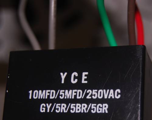
Ceiling fans with pull chains typically include a speed control switch, a direction switch, and a capacitor. Unfortunately, there is no agreement among manufacturers about how to configure these components. The switches come in more than half a dozen configurations. The capacitors come in even more variations, including different numbers of wires, different wire colors, and different capacitance values. Ceiling fan capacitors may have 2 to 5 wires. (Capacitor examples)
The information in this document is based on my experience fixing a ceiling fan with a 3-speed (plus off) switch and a 5-wire capacitor. However, I have also included some information on how to apply these concepts to the general case, so this information may be helpful even if you have a different type of capacitor or switch. This document is intended to be read as a whole. So, even if you are using a different type of fan, please read all the sections because they will help you understand how to figure out your particular ceiling fan.
The specific fan I worked on is an old Hunter type G model 25656 made around 1989.
This section describes the operation of a ceiling fan, based on a couple web sites I read. A typical ceiling fan motor contains two coils. One or both coils may be connected to capacitors. The speed is varied by changing the capacitance in series with one of the coils. (Photos & schematics)
There are several ways that ceiling fan capacitors can be configured. There are two keys to keep in mind. First, increasing the capacitance in series with the coil will typically increase the fan speed. In this regard, note that a short (direct wire, no capacitor) is like an infinite capacitor (for AC power only, not DC). The second key is that you can increase capacitance by putting capacitors in parallel. Capacitors in parallel add. Thus two 5 microfarad (µF) capacitors in parallel are equivalent to a 10 µF capacitor. Note that µF may also be written as uF or MFD.
Here is the solution I used for my particular fan. The basic concepts are probably similar for other fans.
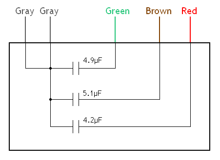
I determined what the internals of the capacitor are. A fan capacitor with more than two wires will probably contain multiple capacitors in one block. The diagram below shows the actual values that I measured. Nominally they may be 5 µF, 5 µF, and 4 µF, although the labeling of the block suggests that all 3 capacitors are supposed to be about 5 µF. Remember that a capacitor can hold charge even when it is disconnected from the power. Therefore it is necessary to discharge the capacitor carefully before touching the wiring. I did this by connecting all the leads. I do not know whether or not this is the best way to do it. After discharging the capacitor, it may be wise to check with a volt meter to make sure no charge remains between any pair of leads. (Note that any stored voltage present in the disconnected capacitor would be DC, not AC.)
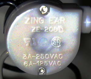
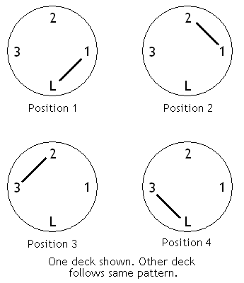
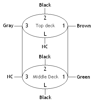
The replacement switch I used was a Zing Ear ZE-208D. It was packaged under the name Harbor Breeze with the item number 033906. It was the only kind they had at the store. The switch has two decks. Electrically, the two decks are not connected with each other. The switch has four positions. In any one position, it connects two adjacent contacts. So, for example, it starts by connecting L and 1 on the top deck and, separately, L and 1 on the middle deck. On the next pull it connects 1 and 2, then 2 and 3, then 3 and L, and finally back to L and 1. The diagram below shows the sequence of switch positions. The switch advances to the next position when you pull the chain. The top and middle decks rotate together but are not connected electrically. (Note: The switch photo is in false color to make the writing legible.) This diagram applies only to this particular switch. Other switch models may have different connection patterns.
In the lower hub of the ceiling fan where the capacitor and switches are located, several wires come down from higher in the fan. For the speed switch and capacitor, the important wires are the black and red ones. Also a gray wire comes from the fan direction switch. The black wire is apparently hot (as usual in household wiring). It branches into the speed switch. The gray wire seems to supply power to one of the motor windings. I am not sure what the red wire does. I think it goes to the other motor winding. The red wire from the fan was connected directly to the red wire on the capacitor, so I left it that way.
The goal is to put a capacitor in series between the black and gray wires. Basically this arrangement puts the input power through a capacitor and then into one of the motor windings. Varying the value of the capacitance changes the speed. For the low setting I used one 5 µF capacitor. For medium I used two 5 µF capacitors in parallel, forming a 10 µF capacitor. Note that the two 5 µF capacitors are in parallel with each other and this combination is in series between the black wire and the motor. For high speed, a capacitor is not used. On high, the gray wire connects directly to the hot wire. This is essentially an infinite capacitance.
The diagram below shows where the wires go on the switch. NC stands for no connection. IMPORTANT: Keep in mind that this wiring is for a particular switch type and a particular fan. Different switch patters will require different wiring.
 This diagram is for one particular switch and fan. Do not use it directly.
The black wires on the diagram are connected to the black wire that comes down from higher in the fan. The black wire from the fan originally branched into two, but it was necessary to add a third to work with this switch. The other wires go to the capacitor. One of the gray capacitor wires goes into the speed switch. The other gray capacitor wire twists together with the gray wire coming from the direction switch. The red capacitor wire twists together with the red wire that comes down from higher in the ceiling fan.
After completing the repair, I noticed than when switching from medium speed to high speed there is sometimes a slight audible "pop" suggesting sparking inside the switch. I do not know if the original switch did this. I am not sure of the cause but there are several possibilities. I do not know if it is hazardous. However, we have been using the fans all summer and there have not been any problems.
Consider the logic behind this wiring. The following table describes what happens in each switch position.
| Position/speed | Connections | Result |
|---|---|---|
| 1/Low | L and 1 (black and green on middle deck) | 5 µF in series between hot (black) and motor (gray from direction switch) |
| 2/Medium | 1 and 2 (black and green on middle deck, black and brown on top deck) | Two 5 µF capacitors in parallel with each other, resulting in a total of 10 µF in series between hot (black) and motor (gray) |
| 3/High | 2 and 3 (black and gray on top deck) | Hot (black) connects directly to motor (gray); remember that both gray wires on the capacitor are connected together inside the capacitor |
| 4/Off | 3 and L | NC on top and middle decks |
The general principles I used might help you analyze other ceiling fans.
Before disconnecting any wires, make sure you write down what the original connections are. Write down exactly where each wire goes. You may want to take a large number of digital photos as well. However, it can be tricky to capture all the details. Taking close-ups in medium light will generally lead to a very small depth of field. A flash can cast sharp shadows that obscure details. Even in a good picture it may be very difficult to read labels engraved or stamped on plastic parts. Therefore, photography should only be a supplement to a hand-drawn diagram.
By far the easiest way to fix a fan is to find an exact replacement switch. You may want to try to contact the manufacturer. Also there are many fan parts sellers online. If you cannot get a replacement, or would rather just try to use whatever switch you can find at a local store, the following information may be helpful.
First of all, if you know the pattern of your original switch it will help greatly. If you know which contacts the switch connects in each speed position, then you can determine by inspection which wires get connected for each speed setting. Then it is just a matter of finding a way to wire your new switch to replicate those connection patterns. For example, if you know that blue and black connect to make high and orange and black connect to make medium (just for example), then you would try to find a way to wire your new switch to make those same connections when you pull the chain. This can be done by drawing a diagram and experimenting on paper. Draw the switch and write wire color names next to each contact in a way that makes sense. Approach it logically. Then verify your design by looking at your diagram and thinking about which wires the switch will connect in each position. (By position, I mean the switch state for each pull of the chain.)
If you do not know the pattern of the original switch and cannot find any information on it, you might consider disassembling the switch (after removing it from the fan, obviously) to see if you can determine the contact pattern.
If you cannot determine the pattern of your original switch or are unsuccessful working from the original pattern, a more in-depth approach is required. You need to determine what the wires coming out of the fan mean. In my fan, several wires hang down from higher up in the fan. These include black, red, white, yellow, and pink. Please remember, these color explanations are only an example of one model of fan. Your fan may have different color wires. Or, even if the wires are the same color on your fan, they may mean different things. What I am describing here is just the logical process I followed for determining what these wires are. I examined these connections along with the operating concepts behind a ceiling fan. I found that the black wire is apparently hot (as usual), and the white is neutral (as usual). The black wire branches into the speed switch. The white wire goes to the middle left of the direction switch. The yellow and pink wires go to the direction switch too. On the top of the direction switch, the yellow is on the right side of the switch and the pink is on the left. On the bottom of the direction switch they are reversed (yellow on left, pink on right). In the middle of the direction switch, the white wire comes into the left side and a gray wire is on the right side. I concluded that the yellow and pink wires are the two ends of one of the motor coils. By flipping the order of the yellow and pink wires (by moving the direction switch), the rotation direction of the ceiling fan is reversed. Since white (neutral) is on the left, the gray wire on the right seems to be the wire through which power is supplied to the motor winding. I am not sure what the red wire does. I think it may go to the other motor winding. In my fan, it originally connected directly to the capacitor and not the speed switch, so I left this connection as it was. At this point, please note that the wire colors in your fan may be different. Information I have read on the Web suggests that there is no standard among manufacturers. The above information about wire colors is not intended to apply directly to any particular fan. Rather, this information is to show you the logic of how to figure out your fan.
Most likely a capacitor needs to be in series between the incoming power and the motor winding. In the case of my fan, as described in the previous paragraph, this means connecting a capacitor in series between the black and gray wires. The speed switch will also be involved of course, since it will determine which capacitor(s) are connected between the black and gray wires.
You also need to know the internal configuration of your capacitor, since ceiling fan capacitors often contain multiple capacitors in one package. If you do not know the internal configuration of your capacitor, you could make measurements to discover it. Important: Remember when working with capacitors that they can store a charge even when not connected to anything. Thus you could get shocked even if the circuit breaker is off. Discharge the capacitor safely and verify that it is discharged (using a volt meter perhaps) before touching the leads with your hands. (With regard to measuring residual voltage on a disconnected capacitor, note that it would be DC.) Since fan capacitors may actually contain multiple individual capacitors in one unit, be aware there could potentially be voltage between any two wires until you discharge it. The approach I took was to measure the capacitance between each possible pair of wires and then draw a diagram. There are many ways to measure capacitance. By far the easiest is to use a capacitance meter. If you cannot find the internal configuration of your capacitor, another approach would be to consider obtaining a new capacitor whose internals you do know.
Once you know the internals of your capacitor block, you need to figure out a switch wiring that will create the desired combinations of capacitors. As an example, let me explain how I created a switch wiring for my fan. For convenience, here is the switch wiring diagram again:
This diagram is for one particular switch and fan. Do not use it directly.
I started by assuming the switch to be in the position that connects L and 1. (Other switches may connect different combinations.) I wanted this position to be low speed, so I wanted a 5 µF capacitor. I started by bringing black (hot) into contact L on the middle deck. Next I decided to use the 5 µF capacitor that is accessible through the green wire on the capacitor block. So, I put green from the capacitor into contact 1 in the middle deck. Remember that the gray wires from the capacitor are connected internally to the other end of the capacitors that are on the green, brown, and red wires (see capacitor internals diagram above). Also, one of the gray wires from the capacitor goes to the gray wire from the direction switch, and from there to the motor. So now I have 5 µF in series between black and gray when the switch is in position L-1. The next position is 1-2, which I wanted to be medium. For medium, I knew I needed more capacitance. I got 10 µF by putting the two 5 µF capacitors in parallel. I already had one 5 µF capacitor connected on the middle deck via the green wire. I needed black to connect with this in switch position 1-2, so I added another black on contact 2 on the middle deck. At the same time, I wanted black and brown connected on the top deck so that I would have the two capacitors in parallel. So I put brown in contact 1 and black in contact 2 on the top deck. Now when the switch is in position 1-2, black connects to green and brown simultaneously. The next position is 2-3, which I wanted to be high speed. So I put the other gray wire from the capacitor into contact 3 on the top deck. Now when the switch is in position 2-3, the black and gray wires connect on the top deck and there is no connection on the bottom deck. Finally, I checked to make sure the remaining position, 3-L, resulted in off. Note that I had to put the gray wire in contact 3 on top because even though the middle deck has black on 2 as well, it also has black on L, which would make position 3-L another high, rather than off. This is just an example of the logical approach required to develop a suitable switch wiring once you know the pattern of your switch and the internals of your capacitor.
Note that all this experimentation with wire positions is done on paper, not with the actual wires. Doing it on paper is much faster, easier, and safer. Verify your wiring choices on paper before making any connections. To check your wiring on paper, carefully trace out what the circuit will be for each switch position.
Remember that capacitors can hold charge even when disconnected from other wiring. Be sure to carefully discharge the capacitor before touching the wires with your hands.
I appreciate feedback, comments, corrections, and questions. I especially like to know when my work is useful to people. However, please know that I cannot provide simple "this color wire goes here" responses to your questions about your particular fan. My e-mail address is provided below.
Comments and questions are welcome. E-mail address: contact delete-this-before-sending _AT_ vobarian.com (Obviously, delete the extraneous words and replace _AT_ with @. This is to reduce spam.)
Mountains & clouds at top of page (clouds.jpg) taken from photo by Oswald Skene / DHD Multimedia Gallery
©2011 Chad Berchek - everything here unless otherwise noted

 Home
Home Ceiling Fan Switch Repair